In today's lecture (session 2), professor mentioned three factors which reduce illumination on the edge of the image. At first, I'm a little confused because so many cosines (four, in total) are multiplied together for the illumination reduction and it's hard to figure it out only by verbal reasoning.
After thinking about it awhile, I tried to explain it using graphs. And this made me feel more comfortable. I hope it may also do help to other guys.

In figure 1, let's first assume that the light source is a sphere. Light emitted from the source is absorbed by the image film.
On the two different spheres, there are two differential area, S1 and S2. Because the distances from them to the light source are different and the irradiance (the incidence flux density, or flux per unit area) is inversely proportional to the distance, the irradiance at S2 is that at S1 multiplied by cos(phi) squared. So distance difference is the first factor contributing to illumination reduction.
But S2 indicated by red is not on the image film but it makes an angle phi with it. So the effective differential area on the film should be added a factor of cos(phi), as indicated by the orange area. Obliquity contributes also.
The above two factors are sufficient to explain illumination for a sphere light source. But in this course we are dealing with lens, which cannot be modeled as a sphere but roughly by a flat circular object like a coin. Figure 2 illustrates this factor.

After we changed the model of the light source, the light beam emitted from the source shrinks from the blue envelope to the yellow envelope. This is because the effective source is an ellipse indicated in orange. The shrink factor is cos(phi).
Combining all the three factors above, the total illumination reduction factor is four cos(phi) multiplied together.
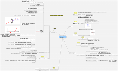
 I have taken my notes from the second session's presentation in a mind map format. If anyone would like to have a copy for their review, just drop me an email and I can send you PDF (36kb) version of it.
